English ![]()

Phone:
No.8, Xinle Road, Xinle Industrial Distric, Ma an Town, Huizhou City, Guangdong, China
Views: 0 Author: Fisher Publish Time: 2024-06-04 Origin: Site
Rexroth A4VG hydraulic pump control valve
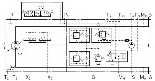
(1) NV - Model without control module
The mounting surface of the control module passes.Machined and equipped with sealing cap plate. Can be used to reconfigure controls
Modules (HD, HW, EP, EZ).When used in a "DA" control system,The spring of the servo cylinder must be assembled
Make appropriate adjustments to the hardware and control panel. Complete, the schematic diagram is shown in Figure 2-3.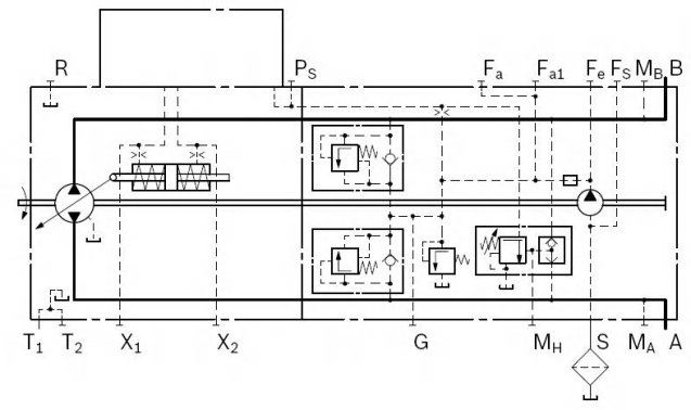
(2) DG — Directly controlled hydraulic control
Pump pilot pressure, via Oil port X1 or X2 directly acts on on the servo piston. The flow direction is given by The pressurized control pressure port determines
determined . See the schematic diagram in the figure 2-4, pump displacement is a stepless variable,Proportional to the control pressure, but also affected by system pressure and pump drive rotation.
The impact of speed. Only when DG controls When the pilot oil is supplied from the ps port,Only available for pressure shut-off valve and DA valve Effective, see Figure 2-5. maximum allowed
Control pressure: 4MPa; It is necessary to check the startup during DG control machine and vehicle parameters.
Figure 2-4:
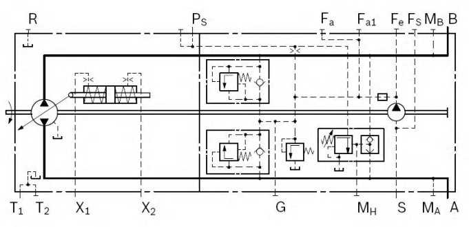
Figure 2-5:
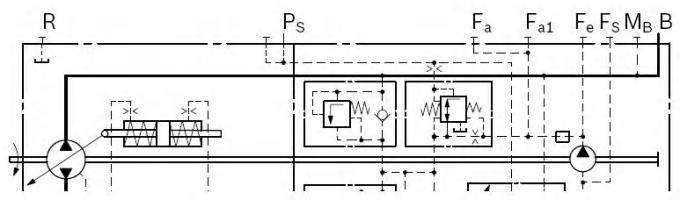
(3) HD – Hydraulic proportional control related to pilot pressure
The output flow rate of the pump is between 0 and Stepless variable between 100%, and control ports (Y1 and Y2) Proportional to the pressure difference. See Figure 2-6,
Lead letter from external source the number is a stress signal. Pilot flow the amount can be ignored, the pilot pressure pushes control valve spool, the spool will control oil inlet and outlet servo cylinder, use
to adjust pump displacement. Synchronized feedback lever any given pilot signal can be
he pump flow rate is maintained within the control range within.
If the pump is also equipped with DA control valve, you can control the traveling transmission
Perform automatic operation, Figure 2-7.
Figure 2-6:
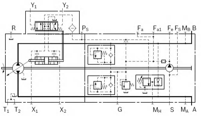
Figure 2-7:
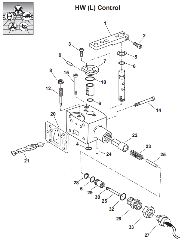
(4) HW — Hydraulic proportional control of mechanical servo
The output flow of the pump is shown in Figure 2-12. The control characteristic of the HW valve is a stepless variable between 0 and 100%, which is related to the swing of the control rod.
Proportional to the angle of motion (0° to ±29°). Pump flow is maintained between 0° and 29° at any given position of the control lever.
If the pump is also equipped with a DA control valve, the traveling drive can be operated automatically. The schematic diagram is shown in Figure 2-11.
HW control valve:
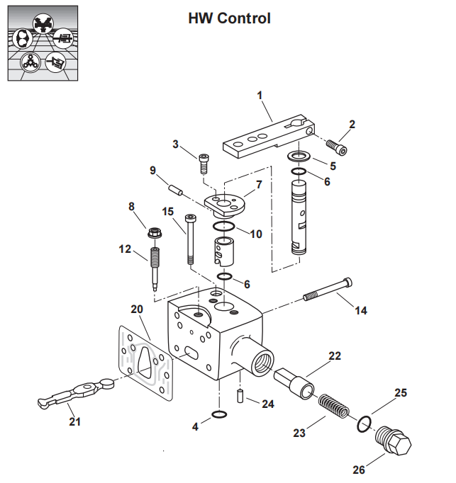
Figure 2-11: 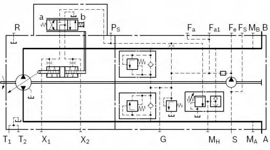
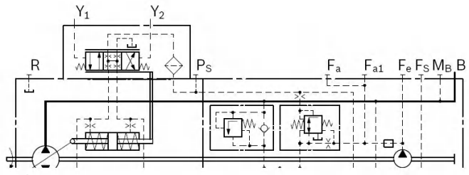
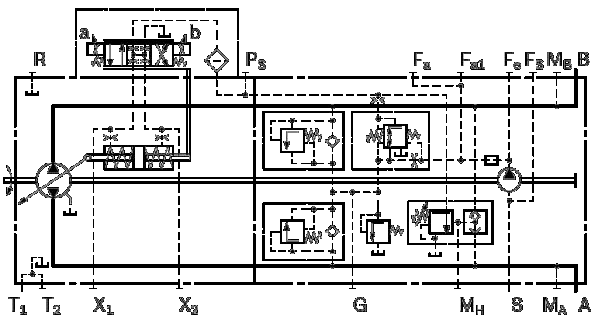
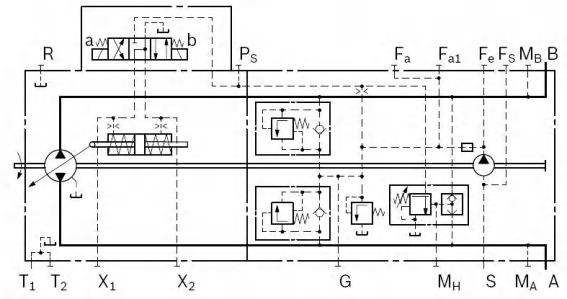
HW(L) control valve:
(5) EP - electrical proportional control
The output flow rate of the pump is between 0 and infinitely variable between 100%, and electrical the current passing through magnet a or b is proportional.
The electromagnetic force pushes the control valve spool;oil import and export servo cylinder, use to adjust pump displacement.
Feedback rod between valve and servo piston keeps pump flow within control range within.the schematic diagram is shown in Figure 2-14.
If the pump is also equipped with DA control valve, the travel transmission can be automatically controlled.
For manual operation, see Figure 2-15.
Figure 2-14:
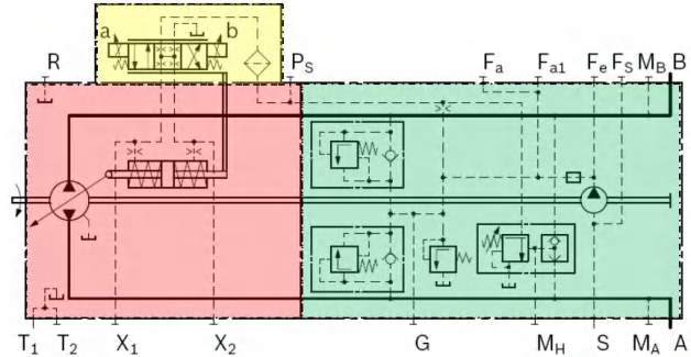
Figure 2-15:
(6) EZ — electronic two-point control
When power is applied, switch solenoid a or
b. The valve core is fully opened and the internal pressure is controlled.
Directly connected to the servo piston and the pump oscillates
to maximum displacement. With EZ control, pump flow
Can be switched between vg 0 and vg max.
EZ valve control schematic diagram:
(7) DA - automatic control related to speed
DA control is related to engine speed and is mainly used in walking transmission systems. The control pressure generated by the DA control valve
The force is proportional to the pump (engine) drive speed and is delivered to the servo piston through the three-position four-way directional valve for the swash plate variable speed.
quantity. Pump displacement is a continuously variable variable and is affected by pump drive speed and system pressure. Output port (e.g. equipment forward or
or back) depends on whether electromagnet a or b is energized.
When the pressure in the pump system increases (such as an increase in equipment load) to a large enough level, it will cause the pump's swash plate to swing back to a smaller position.
displacement, similarly, the engine speed decreases and the control pressure is reduced to achieve engine overload protection (anti-idling).
If the hydraulic pump has power requirements, it will cause the engine speed to drop further. This will further reduce the control pressure,
This results in a reduction in pump displacement. Automatic power allocation and full utilization of available power are achieved in this way, both for
The walking drive can also achieve constant power control.
Various override options are available for the DA control function, ensuring hydraulic control operation at reduced vehicle speeds maintain a higher speed.
DA control is available on pumps with EP, DG, HW and HD control modules to protect the engine from overloading.
DA control is suitable for drive systems but requires checking of engine and vehicle parameters to ensure safe and effective pump use and equipment.
DA valve fixed setting:
Control pressure generation and drive rotation
speed related. However, it is possible to mechanically
Handle (jog function) can reduce control
Pressure, independent of drive speed, see figure
2-20. Maximum drive allowed at handle
The torque is Tmax = 4 Nm. Max spin
Angle is 70°, handle position: any.
Figure2-20: